

Send Message
Privacy statement: Your privacy is very important to Us. Our company promises not to disclose your personal information to any external company with out your explicit permission.

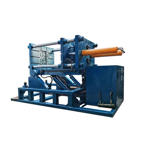
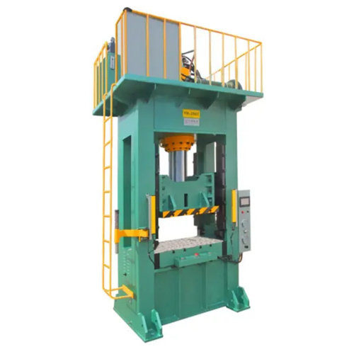
The Roll Round Hydraulic Press is designed for high-precision forming and stable, repeatable performance, with accuracy of up to 98% achievable under optimized operating conditions. Its durable construction, precise hydraulic pressure control, and dependable rolling mechanism support efficient production across demanding industrial applications. By combining strength, consistency, and operational control, this press offers a practical solution for manufacturers seeking improved forming quality and reliable long-term performance.


When I hear a claim that a roll round hydraulic press can reach 98% precision, I ask one question: what does the 98% measure?
A percentage alone does not tell me whether the press can hold a target diameter, maintain forming pressure, repeat the same stroke, or keep the workpiece aligned. These are different performance points. A buyer who treats them as the same may choose a machine that looks suitable on paper but gives uneven results on the shop floor.
For a roll round hydraulic press, precision depends on several parts working together:
The machine may perform well under controlled conditions, but the final part can still vary when the material changes or the setup is not checked.
A more useful way to judge the 98% claim is to convert it into measurable data.
If the target forming diameter is 500 mm, a 98% result could be interpreted in many ways. It might mean the average part reaches 490 mm, which is not the same as holding a 500 mm target within a small tolerance. It might refer to a success rate across a batch. It might describe repeatability under one set of conditions.
None of these meanings proves that every part will meet the same dimensional requirement.
I would ask the supplier to define the claim with figures such as:
A useful test report may look like this:
Target diameter: 500 mm
Material: mild steel
Thickness: 6 mm
Test quantity: 20 pieces
Measured range: 499.2–500.8 mm
Maximum deviation: ±0.8 mm
This information gives me a clearer picture than “98% precision.” It shows how the press performed with a stated material and setup.
The phrase “roll round” also needs attention. Some machines use rollers to guide or shape the workpiece during pressing. The roller path, roller diameter, gap setting, and frame structure can affect the final shape. If one roller sits slightly out of alignment, the part may show taper, uneven curvature, or a flat section.
I would inspect the machine through four practical checks.
1. Check the frame and roller alignment
A strong frame helps reduce movement under load. I would look at the frame welds, roller supports, guide rails, and the distance between the rollers. A simple alignment check with a calibrated straightedge or measurement tool can reveal gaps that are not visible during a quick visit.
The rollers should stay parallel through the working range. If they shift as pressure rises, the press may produce different results at low and high loads.
2. Review the hydraulic control
Hydraulic pressure is not the same as forming accuracy. A gauge may show the applied pressure while the material still moves in an uneven way. Pressure fluctuation, cylinder wear, oil temperature, and valve response can affect the stroke.
I would ask whether the system records pressure during the cycle. A stable pressure curve gives more useful information than a single gauge reading.
The cylinder should also return to a repeatable position. If the stroke varies by even a small amount, the finished shape may change across the batch.
3. Test repeatability
I would run several pieces with the same settings instead of checking only one sample.
For example, a workshop forming 20 steel rings can record:
If the results stay close to the target, the press shows useful repeatability. If the operator must adjust the machine after every few parts, the 98% claim may not match normal production use.
A single successful sample does not show batch performance.
4. Measure the finished workpiece correctly
The measuring tool must match the tolerance. A basic tape measure may be suitable for rough checking, but it cannot support a tight dimensional claim. A vernier caliper, height gauge, radius gauge, or coordinate measuring system may be more suitable, depending on the part.
The measurement method should remain the same for every test piece. Different tools or different measuring points can create results that look inconsistent even when the press is working normally.
Material behavior creates another limit. Two steel plates with the same stated thickness may respond differently because of hardness, grain direction, surface condition, and internal stress. Aluminum, stainless steel, and mild steel also need different settings.
This is why I do not treat machine accuracy as a fixed number that applies to every job. A press may hold a narrow tolerance with one material and show a wider range with another.
A workshop example makes this easier to understand.
A small fabrication shop needed to form curved steel sections for storage equipment. The target shape was consistent, but the material arrived from different batches. The operator noticed that the first batch required three passes, while the next batch required four. The machine itself had not changed. The material response had changed.
The shop began recording material thickness, pressure, roller gap, and the number of passes. After several production runs, the operator created a setting sheet for each material type. The finished parts became more consistent, and rework fell. The improvement came from process control, not from relying on a percentage printed in a brochure.
For buyers, a practical acceptance test may include:
I would also ask about maintenance. Hydraulic oil, seals, valves, bearings, rollers, and guide parts all affect repeatability. A press that performs well when new may need regular checks to keep the same working condition.
The service answer matters as much as the machine specification. I want to know which parts are available, how alignment is checked, what the warranty covers, and whether the supplier can support a repeatability test after installation.
So, can a roll round hydraulic press really reach 98% precision?
It may reach a high level of repeatability under defined conditions, but the phrase “98% precision” is not enough to confirm that. The claim needs a clear definition, a stated tolerance, a material specification, and test results from repeated parts.
My view is simple: judge the press by measured deviation, not by a rounded percentage. A machine that produces 20 consistent parts within the required tolerance is more useful than a machine promoted with a large number that has no test method behind it.
When I work with a hydraulic press, I look for more than pressing force. I need steady movement, controlled pressure, safe positioning, and repeatable results. A press may have enough capacity on paper, yet still create problems if the frame shifts, the ram moves unevenly, or the operator cannot place the workpiece with care.
That is where a roll-around hydraulic press can be useful. Its wheeled frame allows me to move the press toward the job instead of carrying heavy parts across the workshop. The design combines mobility with the control expected from a fixed shop press.
The phrase “98% precision” needs a clear explanation. It should not be treated as a universal performance guarantee. Precision depends on the material, tooling, pressure setting, operator technique, and measurement method. A workshop may use 98% as an internal target after comparing repeated pressing results with a reference value. Buyers should ask how that figure was tested before using it in a purchase decision.
I usually assess a roll-around press through several practical points.
A strong frame helps keep the pressing line steady. When the frame bends or shifts under load, the force may not reach the workpiece evenly. That can lead to slanted bushings, damaged bearings, or unevenly formed parts.
The ram should move in a controlled path. Smooth travel makes it easier to stop at the right point and reduce sudden force changes. A pressure gauge can help me monitor the load, yet the gauge alone does not create precision. The cylinder, pump, seals, frame, and tooling all affect the result.
A movable press also needs a reliable locking system. Wheels make shop layout easier, but the machine should remain stable during operation. I look for locking casters, wide support points, and a base that matches the working load. A mobile press that moves while pressing can create a safety problem and affect the quality of the part.
Table height matters when I handle parts of different sizes. An adjustable bed lets me set the workpiece at a comfortable level and reduce unnecessary gaps between the ram and the tooling. Less empty travel can make the process easier to control. I still check that the table pins, supports, and frame are rated for the intended load.
Tool alignment deserves close attention. A press can deliver steady force, but a poorly centered tool may place pressure on one side of the part. I use flat supports, suitable adapters, and a centered load path. For bearing removal, for example, the support should hold the surrounding housing while the ram acts on the correct inner or outer race. Pressing against the wrong surface can damage the part before the operator notices.
A small repair shop offers a useful example. The shop handles bushings, shafts, and bearings from agricultural equipment. The old fixed press worked well for large jobs, yet workers had to move heavy assemblies to one corner of the building. The roll-around design allowed them to position the press beside the repair bench. After setting the brakes, checking the support height, and centering the tool, the operator could complete the job with fewer movements and better visibility.
The result was not simply faster work. Operators had more control over the setup, and the risk of lifting a heavy assembly was reduced. The shop still needed proper measurement and inspection. A mobile frame could not replace correct tooling or trained operation.
I recommend a simple check before purchase:
A press that meets every basic specification may still be a poor fit if its controls are hard to read or its bed is difficult to adjust. I prefer a machine that makes correct setup easy. Clear controls, stable support, and visible alignment often affect daily results more than a large capacity number.
Roll-around hydraulic presses stand out when a workshop needs controlled force near different work areas. Their value comes from a mix of mobility, frame support, pressure control, and practical setup. A claim such as 98% precision can be useful when the test method is shown and the working conditions are clear. It should guide questions, not replace them.
For my buying decision, repeatable performance matters more than a strong marketing phrase. I check how the press behaves with the parts I actually handle, how safely it can be moved, and how easily the operator can control each pressing step.

Many production lines lose time for a simple reason: round workpieces do not always sit in the same position. A tube, ring, pipe section, or cylindrical shell can shift during pressing. The result may be uneven forming, surface marks, repeated adjustments, or extra inspection work.
A roll round hydraulic press can help solve this problem by combining controlled hydraulic force with a support system designed for round parts. I see it as a practical production upgrade for workshops that need steadier forming without changing their whole manufacturing process.
When I work with round metal parts, I pay attention to three points:
A flat press table may be suitable for plates and blocks, but round parts can move under load. A small shift can affect the pressing angle or the final diameter. If the operator needs to reposition the part several times, output becomes less stable.
Manual correction also creates differences between batches. One operator may apply pressure in a slightly different way from another. These small changes can show up during welding, assembly, or quality inspection.
A roll round hydraulic press uses hydraulic power to deliver controlled force. Rollers or round-part supports help keep the workpiece aligned while pressure is applied.
The machine does not remove the need for correct setup. It gives the operator a more stable working platform.
The main benefits can include:
For a workshop producing pipe fittings, for example, the press can help maintain alignment while a tube section is shaped or corrected. The operator still needs to check the material, tooling, pressure setting, and support position before the cycle starts.
Imagine a metal fabrication shop making curved pipe sections for industrial frames.
The shop previously used a general hydraulic press with temporary blocks. The setup worked for small orders, yet the blocks needed frequent adjustment. Some pipe sections came out with slight angle differences, which created extra fitting work during assembly.
After moving to a press with round-part rollers and adjustable supports, the operator could position each pipe section more consistently. The forming process became easier to repeat. The team still inspected every batch, but fewer parts needed correction after pressing.
This type of result depends on the material, tooling, machine capacity, and operator setup. A press alone cannot fix poor dies, incorrect pressure, or unsuitable support points.
I do not choose a hydraulic press by tonnage alone. A machine may have enough force but still fail to suit the production task.
I check the following details:
Workpiece diameter
Measure the smallest and largest round parts that will pass through the working area. Check whether the roller spacing can handle the full range.
Material and thickness
Steel pipe, stainless steel tube, aluminum sections, and other materials respond differently to pressure. Wall thickness also affects the force needed and the risk of deformation.
Required forming method
Some jobs need straightening. Others need bending, pressing, fitting, or diameter correction. The tooling and roller layout should match the actual operation.
Working stroke and opening height
The hydraulic cylinder must have enough stroke for the job. The available opening height affects loading, unloading, and die installation.
Control system
A manual valve may suit low-volume work. A controlled system with pressure adjustment and repeatable settings may be more useful for batch production.
Safety features
Look for guarded moving areas, emergency stop access, stable frames, pressure control, and clear operating instructions. The operator should understand how to stop the cycle before production begins.
I recommend creating a simple setup record for each common workpiece.
Record:
The operator can use the record as a reference for repeat orders. This reduces guesswork when the same pipe or ring returns to the line.
A test piece should be pressed before a full batch starts. Measure the diameter, angle, length, or other required dimension. Check for dents, cracks, flattening, and surface marks. If the test part is not acceptable, adjust the support or pressure before more material is processed.
Precision does not come from machine design alone. Maintenance has a direct effect on results.
Keep the rollers clean and check them for wear. Inspect hydraulic hoses, seals, oil levels, and pressure readings. Loose guides or damaged tooling can create uneven force. A small defect in a roller may leave marks on every workpiece that passes through the machine.
A maintenance log can include the operating hours, oil checks, roller condition, hydraulic leaks, and unusual noise. This gives the production team a clear record when the machine needs service.
A roll round hydraulic press makes sense when round parts are already part of your daily work and the current process depends on temporary supports, repeated repositioning, or manual correction.
It may not be the right choice for every shop. A business that only presses flat plates may gain more from a different press design. The correct decision should come from the workpiece range, production volume, forming method, and required tolerance.
When the press, tooling, rollers, and operator process are matched well, the production line becomes easier to control. The goal is not simply to add hydraulic force. The goal is to hold the round workpiece in a stable position, apply pressure with control, and make the result easier to repeat.

When a curved part comes out uneven, the problem is rarely limited to the final bend. Small errors in material thickness, roller spacing, pressure, or alignment can affect the whole batch. Rework takes time, and repeated adjustments make production harder to control.
A roll round hydraulic press can help create a more repeatable forming process. Its hydraulic system applies controlled force while the rollers guide the material through a curved path. For buyers who need cleaner results, the key question is not only how much pressure the machine can produce. The useful questions are:
A stated accuracy target of 98% may attract attention, yet I would treat it as a test result rather than a fixed promise. Actual results depend on the material, tooling, operator settings, and inspection method. Ask the supplier how the figure was measured and under which working conditions.
The machine uses hydraulic force to move or support forming tools while the workpiece passes through the rollers. This setup can be used for parts such as:
The process gives me more control than a basic manual setup. I can adjust pressure gradually instead of applying force all at once. That helps reduce sudden marks and uneven curves, especially when the material needs careful handling.
A press may have a strong hydraulic system, but pressure alone does not create a clean result. The workpiece must stay centered. The rollers must remain at the correct distance. The material also needs a suitable thickness and shape before forming begins.
I would check these points before placing an order:
Roller alignment
Misaligned rollers can create a curve that changes from one side to the other. Ask how the machine keeps the rollers in position during use.
Pressure control
A pressure adjustment system helps the operator make small changes between forming passes. This can be useful when working with different metals.
Working range
Check the maximum width, thickness, diameter, and material length. A machine that suits one part may not suit another.
Control panel
Clear controls reduce setup mistakes. A simple interface can be more useful than a long list of functions that the operator rarely uses.
Measurement method
Ask how the supplier checks the finished curve. A result measured with a basic ruler may not match a result checked with a calibrated gauge.
Imagine a workshop making curved steel frames for equipment covers. The operator forms ten pieces from the same material batch. Three pieces need extra correction because the curve changes near the edge.
With a roll round hydraulic press, the operator can record the roller gap, pressure level, and number of passes used for an acceptable piece. The same settings can guide the next batch. The result may still need inspection, but the process becomes easier to repeat.
This example does not mean every workshop will reach the same accuracy. Material hardness, springback, tool wear, and operator skill can change the result. A test piece should be made before regular production starts.
I would prepare a short list of questions for the supplier:
A supplier that gives direct answers makes the purchase easier to assess. I would also request sample results linked to a material and part size close to my own work.
Hydraulic forming equipment should be used by trained operators. The work area needs enough space for loading, unloading, and inspection. Guards should remain in place during operation, and the machine should be checked for leaks, loose parts, and unusual noise.
Material should sit correctly on the rollers before pressure is applied. Hands should stay away from moving parts. A written setup guide can help different operators follow the same process.
Cleaner results come from a complete system: suitable machine capacity, controlled pressure, correct alignment, repeatable settings, and regular inspection. A roll round hydraulic press may support that process, while the stated 98% accuracy figure should be reviewed against your own material and production needs.

Many forming jobs begin with the same problem: the material must take a round shape, yet the result needs to stay consistent from one part to the next. Manual force can create uneven curves, surface marks, and extra correction work. A roll round hydraulic press addresses this challenge by combining controlled hydraulic pressure with rolling or round-forming tooling.
I look at this type of press as a force-control system, not just a powerful machine. The result depends on the frame, cylinder, tooling, material, pressure setting, and operator method. When these parts work together, the forming process becomes easier to repeat and easier to check.
A roll round hydraulic press applies pressure through a hydraulic cylinder while the workpiece moves against a die, roller, or shaped tool. The tooling guides the material toward the required curve.
The machine may be used for tasks such as:
The exact result depends on the machine structure and tool design. A press made for tube bending may not suit thick plate forming. A unit designed for small rings may not provide the working space needed for large profiles.
That is why I check the material and part drawing before I discuss press capacity.
Material behavior changes under pressure. Mild steel, stainless steel, aluminum, copper, and heat-treated parts do not react in the same way.
I usually review these points:
Springback is a common source of size variation. The material may move back slightly after the cylinder retracts. If I set the tool only for the visible curve under pressure, the finished part may open beyond the target size.
A test piece helps reveal this behavior before the full batch begins.
A frame must support the working load without excessive movement. The working area also needs enough space for loading, rolling, inspection, and tool changes.
When I compare machines, I review:
Rated force alone does not tell me whether a press will perform well. A high-force machine with poor access can slow down the job. A compact machine may suit small parts but limit larger workpieces.
The useful question is simple: can the press apply the required force at the required position while keeping the part stable?
The tool often has more influence on the finished part than the pressure setting. A die that is too narrow may leave marks. A die with the wrong radius can create a curve that does not match the drawing.
I check the following before production:
For parts with a visible outer surface, I prefer smooth contact areas and clean support points. A small piece of dirt between the tool and workpiece can leave a mark that is hard to remove later.
Applying full pressure at the start can deform the part too quickly. It can also damage the tool or create a shape that is difficult to correct.
My normal setup method is gradual:
A pressure gauge helps, but pressure is not the same as finished size. Two parts made from different materials may need different settings even when their dimensions are similar.
I record the pressure range, number of passes, tool position, and measured result. These notes give the operator a useful starting point for the next batch.
A small fabrication workshop needs to form steel rings for support frames. The rings are made from flat bar, and the finished diameter must remain within the shop’s drawing tolerance.
The operator begins with one test piece. The first pass creates a partial curve. After the part is measured, the operator makes another pass with a small tool adjustment. The finished ring is checked at several points around the circumference rather than at one location only.
The check shows a small difference between the welded joint and the rest of the ring. The operator adjusts the forming sequence and supports the joint area more carefully. The next test piece has a more even shape.
This example shows why a repeatable method matters. The press provides force, but the operator still needs to control material position, forming steps, and inspection.
Several issues appear often during round-forming work.
Uneven curvature
This may come from off-center loading, inconsistent passes, or a tool with an unsuitable radius. Marking the center line on the workpiece can help the operator keep the part in position.
Surface marks
Dirty tools, sharp edges, or excessive local pressure can damage the surface. Cleaning the contact areas and checking tool edges should be part of the setup.
Part opening after forming
This is usually linked to springback. A test piece can show how much extra forming is needed. The correction should be controlled rather than based on guesswork.
Hydraulic pressure loss
A falling pressure reading may point to a leak, worn seal, blocked filter, or pump issue. Continuing to run the machine without checking the cause can affect both safety and part quality.
Part movement during pressing
Poor support creates a risk of uneven forming. The workpiece should be supported against movement without placing hands near the pressure zone.
A hydraulic press needs regular checks even when it appears to work normally. I inspect hoses, fittings, cylinder seals, guides, rollers, and electrical controls. Oil level and oil condition also matter because contaminated fluid can affect valve movement and cylinder response.
The maintenance record can include:
Any maintenance work should follow the machine supplier’s instructions. Pressure must be released before work begins, and stored energy must be controlled.
A round-forming press can create pinch points and stored hydraulic energy. Operators need clear access to the controls and a safe method for loading the material.
I keep hands away from the forming zone, use suitable handling equipment for heavy parts, and confirm that guards and emergency controls are working. Loose clothing, damaged tools, and unstable supports create avoidable risks.
Training should cover the machine controls, material limits, tool changes, emergency action, and inspection method. A short setup checklist can prevent mistakes when several operators use the same press.
A roll round hydraulic press becomes useful when its force, tooling, and operating method match the part being formed. The machine does not replace measurement or process control. It gives the operator a stable way to apply pressure, repeat a forming sequence, and correct small variations before they affect a larger batch.
When I select or use this equipment, I focus on three points: the material must suit the forming method, the tool must guide the required shape, and every pressure step must remain under control. That approach helps reduce rework while keeping the forming process clear for the people who run it.
A 98% precision result sounds attractive, but the number alone does not tell me enough. Precision may refer to repeatability, dimensional accuracy, surface alignment, or the percentage of parts that meet a chosen tolerance.
When I evaluate a roll round hydraulic press, I look at the full forming process. Material thickness, steel grade, tool condition, hydraulic pressure, rolling speed, operator settings, and measurement method all affect the result.
A well-set machine can help produce consistent round and curved components. It cannot remove every source of variation.
Before choosing a machine, I define the target in measurable terms.
For example:
A workshop may describe its process as 98% precise when 98 out of 100 parts meet the target size. Another supplier may use the same number to describe a measurement close to the design value. These are different claims.
I prefer to ask for:
This approach gives me useful information instead of relying on one large percentage.
A roll round hydraulic press uses hydraulic force to shape material while rollers or guided tooling help control the forming path. The machine is often used for curved plates, rings, tubes, ducts, tanks, and other round components.
Its main value comes from control.
Hydraulic pressure can be adjusted to suit the material. A guided rolling path can reduce sudden movement. A stable frame can help keep the workpiece aligned. Repeatable settings can also reduce differences between one operator and another.
The result depends on the complete setup. A strong press with worn rollers may deliver poor results. A smaller machine with suitable tooling and careful inspection may perform more consistently.
Imagine a fabrication shop making curved steel sections for industrial ducting.
The shop needs to form plates with:
The operator records the material grade, plate size, pressure setting, and rolling passes. The first part is measured with a radius gauge and a digital measuring tool. The operator then adjusts the forming pressure and rolling path before making the next sample.
After several trial pieces, the shop may find that most parts fall within its selected tolerance. That result is more useful than simply saying the machine offers 98% precision.
The example also shows why machine settings and inspection work together. The press shapes the material, while measurement confirms whether the result is acceptable.
Steel, aluminum, and other metals behave differently during forming. Thickness, yield strength, hardness, and grain direction can change the amount of force required.
I record the material information before setting the press. Using the wrong forming data may lead to excess pressure, uneven curves, or surface marks.
Tool width, roller diameter, contact surface, and support position affect the final shape.
A tool that works well for a thick ring may not suit a thin plate. The workpiece should sit securely without excessive contact pressure. Correct tooling also helps reduce unwanted deformation near the edges.
More pressure does not always create a better result. Excess force may leave marks, distort the part, or increase stress in the material.
I prefer a controlled trial. The operator forms a sample, measures it, checks for surface damage, and adjusts the pressure in small steps.
Uneven feeding can produce a tapered curve or misaligned joint. The plate should enter the rollers in a stable position, with support placed according to its size and weight.
A steady rolling speed gives the operator more control. Very fast movement may reduce forming consistency, while an unsuitable slow cycle may increase handling time.
Many metals move slightly toward their original shape after pressure is released. This effect is known as springback.
The amount varies with material type, thickness, radius, and forming method. I measure the part after release instead of judging the shape while pressure remains on it. A small amount of over-forming may be needed, based on test results.
Measurement should match the part.
A radius gauge may suit curved sections. A digital caliper can check width or thickness. A measuring arm, template, or coordinate system may be useful for larger components.
Inspection records can show whether the issue comes from material variation, tooling wear, operator settings, or machine alignment.
I ask the supplier to provide clear technical information:
A sample test is useful when the part has a tight tolerance or a complex shape. It allows me to compare the drawing with the actual formed piece.
It may be possible under a defined production process, but the number should not be treated as a standard result for every job.
The machine needs suitable tooling, correct settings, trained operation, stable material, and a clear inspection method. Part geometry also matters. A simple ring may be easier to repeat than a large curved plate with changing thickness.
My view is simple: a roll round hydraulic press should be judged by measured results, not by a percentage used without context. When the target, tolerance, material, and inspection method are written down, the 98% claim becomes easier to understand and verify.
Interested in learning more about industry trends and solutions? Contact Hu: dgliheng168@163.com/WhatsApp +8613509684273.
International Organization for Standardization | 2010 | Hydraulic Fluid Power General Rules and Safety Requirements for Systems and Their Components
American Society of Mechanical Engineers | 2020 | Jacks Industrial Rollers and Hydraulic Presses
International Organization for Standardization | 2014 | Test Code for Machine Tools Determination of Accuracy and Repeatability of Positioning Axes
Mikell P Groover | 2020 | Fundamentals of Modern Manufacturing Materials Processes and Systems
Serope Kalpakjian and Steven R Schmid | 2014 | Manufacturing Engineering and Technology
Erik Oberg and Franklin D Jones | 2020 | Machinerys Handbook Standard Reference for Manufacturing and Mechanical Engineering Practice
Meet 40T, a fast, precise, and reliable solution built to perform when it matters most. Designed for consistent operation and dependable results, 40T combines speed, accuracy, and stability to help
Upgrade Your Shop with 40T Power and experience dependable performance built for demanding work. Designed to deliver impressive strength, consistent results, and reliable operation, 40T technology
The 40T Hydraulic Press is built for demanding industrial pressing applications, delivering powerful force, dependable operation, and precise control. Its robust construction supports consistent pe
Say goodbye to frustrating jams and experience smoother, more reliable performance with 40T. Designed to help keep operations running efficiently, 40T delivers dependable results when you need them
Email to this supplier

September 22, 2026

September 21, 2026
Contact

Send Inquiry
PRODUCT CATEGORIES
Privacy statement: Your privacy is very important to Us. Our company promises not to disclose your personal information to any external company with out your explicit permission.
Fill in more information so that we can get in touch with you faster
Privacy statement: Your privacy is very important to Us. Our company promises not to disclose your personal information to any external company with out your explicit permission.