

Send Message
Privacy statement: Your privacy is very important to Us. Our company promises not to disclose your personal information to any external company with out your explicit permission.

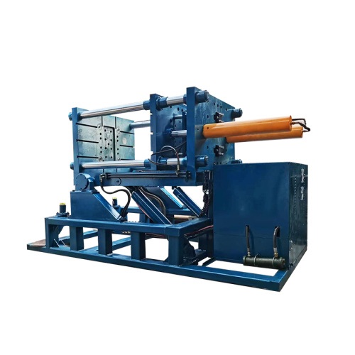
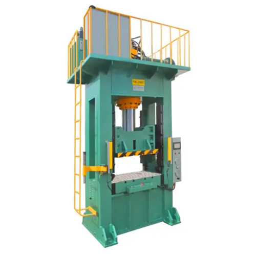
The 50T Press combines powerful 50-ton force with an ultra-fast 10-second cycle time, delivering consistent, high-precision results in every operation. Designed for demanding production environments, it helps improve throughput, reduce processing time, and maintain reliable quality from the first part to the last. For manufacturers seeking speed, accuracy, and dependable performance, this press provides an efficient solution built to keep production moving.


When I run a busy fabrication line, I need a press that can handle steady workloads without making each operator guess the result. A 50-ton capacity gives me room for many forming, bending, pressing, and assembly tasks. A 10-second cycle can help keep work moving, provided the material, tooling, stroke length, and operator process match the machine setup.
The main concern is not speed alone. I also need repeatable pressure, stable alignment, clear controls, and a safe way to load and unload each part.
A 50-ton press can support tasks such as:
The correct capacity depends on the job. A part that needs 20 tons of force may work comfortably on a 50-ton machine. A part that needs force near the press limit may require a different setup, stronger tooling, or a larger press. I prefer to confirm the required force before production begins instead of relying on a rough estimate.
A short cycle time also needs a clear definition. The 10-second figure may refer to the pressing movement rather than the full work cycle. Loading the part, positioning the fixture, pressing, releasing pressure, and removing the finished part can take more time. My actual output depends on the full sequence.
A practical workflow looks like this:
I pay close attention to alignment. A part can look simple, yet a small offset may create uneven force, tool wear, or damage to the workpiece. A stable table and properly matched tooling help keep the load centered.
For example, imagine a repair shop replacing bushings on a series of brackets. The operator places each bracket into a fixture, checks that the bushing is centered, applies the set pressure, and confirms the final position with a gauge. If the pressing movement takes about 10 seconds, the complete cycle may take 20 to 30 seconds after loading and inspection. That estimate gives the shop a more useful production plan than the press movement alone.
Repeatability also depends on maintenance. I check hydraulic lines, fittings, fluid levels, guards, controls, and pressure readings as part of the regular service routine. I inspect tooling for cracks, deformation, and wear. A clean working area makes it easier to spot leaks and keep parts correctly positioned.
Operator training matters as much as the machine rating. Each person should know the safe loading area, hand clearance rules, emergency stop procedure, and limits of the selected tooling. The press should be used within its rated capacity, with suitable guards and workholding equipment.
For my work, the value of a 50-ton press is the balance between force and control. The 10-second pressing cycle can support a steady process, while repeatable settings help reduce variation between parts. I would judge the machine by the complete workflow: capacity, cycle behavior, alignment, control response, service needs, and the quality of the finished part.

When production slows down, the cause is not always the machine itself. Uneven pressure, manual adjustments, material changes, and repeated rework can reduce output and affect product quality.
I look at three needs when choosing a 50T hydraulic press:
A 50T press can support tasks such as metal forming, part assembly, bearing installation, straightening, and controlled compression. The right result depends on the material, die design, stroke length, pressure setting, and operator setup. The force rating should match the actual process instead of being treated as a guarantee for every application.
A stable hydraulic system helps the press apply pressure in a controlled way. This can reduce variation between parts and make the work easier to monitor.
I prefer a setup where the operator can adjust pressure and stroke settings according to the material. A lower setting may suit thin sheet metal, while a higher setting may be needed for tougher components. The machine should provide enough control for the task without adding unnecessary steps.
“100% accuracy” is not a practical claim for every production environment. Accuracy changes with tooling, material tolerance, machine condition, and measurement method.
A better approach is to build repeatability into the process:
This method helps the operator find changes early. It also gives the team a clear reference when the material or tooling changes.
A fabrication shop producing small metal brackets may use a 50T hydraulic press for forming and hole alignment. If each operator sets the pressure by feel, the brackets can show different bends or require extra correction.
The shop can improve consistency by using a fixed fixture, a marked stroke position, and a pressure setting tested with sample parts. The press does not remove every source of variation, yet it gives the team a more controlled process to manage.
The press capacity is only one part of the decision. I also review:
A machine that fits the workspace and production task is easier to use over time. Clear operating steps also help reduce setup mistakes between shifts.
Output improves when the machine, tooling, material, and work method support each other. A 50T hydraulic press can provide strong forming capacity and repeatable operation, but the final accuracy should be confirmed through testing and measurement.
I recommend checking sample parts before full production, keeping process settings on record, and reviewing results after tooling changes. This creates a practical path toward stable output without relying on broad promises.

When a project moves from design to production, small delays can create larger problems. A part may fit in a digital model yet fail during assembly. A short delivery plan may leave too little time for testing. Unclear updates can make it hard to know whether the order is on schedule.
I focus on three practical needs: a clear production path, stable quality checks, and communication that helps you make decisions with confidence.
I begin by reviewing the drawings, specifications, materials, tolerances, and expected quantity. If a dimension appears difficult to produce or may raise the cost, I explain the concern before work starts. A short discussion at this stage can prevent changes after machining has begun.
The production process can include:
Precision depends on more than a machine setting. Tool condition, material quality, fixture design, cutting parameters, and inspection methods all affect the result. I pay attention to these details throughout the order instead of checking only at the end.
For example, a small equipment maker may need a set of aluminum housings for a new control unit. The design may include several mounting holes, a thin wall, and a tight fit around an internal component. A production review can identify the areas most likely to cause trouble. The team may adjust the fixture, confirm the hole position with a sample, and inspect the first piece before producing the full batch.
This approach helps reduce repeated work and gives the customer useful information before the order reaches a larger production stage.
Speed also needs a clear process. Fast production does not mean skipping inspection or accepting unclear specifications. It means removing avoidable waiting time. Complete files, confirmed materials, agreed tolerances, and direct feedback help keep the work moving.
I keep project communication focused on details that affect production:
My goal is to make production easier to follow from the first quote to the finished shipment. You should know what is being made, how it is checked, and what information is needed from your side.
Every project has its own limits. Part size, material, surface finish, order quantity, tolerance, and delivery location can change the suitable process. I do not treat one production method as the right choice for every design. A practical solution should match the part, the batch size, and the use of the finished product.
When you need production support, share the drawings, quantity, material requirements, tolerances, and target schedule. I can review the details, point out possible production issues, and suggest a clear path from design to finished parts.
Fast delivery matters. Precise parts matter more when they need to fit, work, and remain consistent across a batch. A production process built around clear information and steady checks gives both needs the attention they require.
Long cycle times create pressure across a production line. Orders wait in queues, operators rush near shipment dates, and quality checks become harder to manage. Cutting production time can help, but removing checks or pushing people to work faster often creates rework, returns, and added cost.
I see better results when cycle time and quality are managed as one process. The aim is not to make every task faster. The aim is to remove waiting, repeated work, unclear decisions, and avoidable errors.
I begin by mapping the complete workflow, from material receipt to final inspection. I record:
This often reveals a gap between work time and total lead time. A part may require only 20 minutes of actual processing but remain in the factory for several hours while it waits for materials, instructions, or machine access.
A simple process map gives the team a shared view. It also prevents the common mistake of improving one workstation while creating a larger queue somewhere else.
The slowest step is not always the main constraint. A machine may run slowly, but a nearby inspection station may create the longer delay. A team may finish work quickly, while finished items wait for a supervisor’s approval.
I look for:
Once the constraint is visible, improvement work becomes more focused. Reducing time at a station that does not limit flow may have little effect on the total cycle.
Changeovers can take a large part of a shift. Tools, fixtures, settings, cleaning, and test runs all add minutes.
I separate changeover work into two groups:
Preparing tools, materials, and settings before the stop can reduce idle time. Clear fixture storage and labeled connection points also help operators avoid searching.
A useful example comes from the SMED method used in lean manufacturing. The method focuses on moving as many setup tasks as possible outside the machine stoppage. The exact result depends on the process, but the principle is practical: prepare before the line stops.
A faster process does not help if defects move downstream. I prefer checks at the point where an error can be corrected with little effort.
This may include:
Toyota’s production system is widely associated with stopping or slowing a process when a quality problem appears. The purpose is to prevent a small issue from becoming a large batch of defective products. This approach may appear slower at one moment, but it can reduce rework and inspection load across the full process.
When each operator follows a different method, cycle time varies. Quality varies with it.
I document the safest and most efficient known method, then make it easy to follow. A useful standard work sheet can show:
The standard should support the operator, not become a long manual that nobody reads. Photos, simple diagrams, and short instructions often work better than dense text.
A dashboard with too many numbers can slow decisions. I focus on a small set of measures:
First-pass yield shows how often work passes without correction. This measure connects speed and quality more clearly than output alone.
For example, a line that produces 500 units but sends 60 units back for rework may look productive on paper. A line that produces 470 units with very little rework may create better usable output.
I avoid changing the entire line from a single meeting. A small trial gives the team a safer way to check the idea.
The trial can cover one product, one shift, or one workstation. I compare the old and new method using the same measures. I also ask operators what became easier or harder. Their experience often reveals problems that production data does not show.
A packaging company may discover that a new layout reduces walking but places labels farther from the operator. The next adjustment can keep the shorter walking route while moving labels closer to the point of use. Small tests make this type of correction easier.
Cycle-time work often loses momentum when nobody owns the next action. I assign a person to each improvement, set a review date, and record the result in a simple format:
I also check whether the improvement remains stable after several production cycles. A short-term gain that depends on extra effort may not be suitable for regular work.
The most reliable approach is to remove wasted movement, reduce waiting, prepare changeovers, prevent errors at the source, and use data that reflects usable output. When quality checks remain part of the process, shorter cycle times do not need to come from rushed work. They come from a smoother flow with fewer interruptions and less rework.
When a production line handles small metal parts, speed alone does not solve the real problem. The press must also hold the target dimensions, protect the material, and support a steady workflow.
A machine that runs quickly but produces uneven parts can create extra inspection work, scrap, and delays. I look at high-speed precision pressing as a balance between cycle time, force control, tooling, material flow, and operator safety.
The right setup helps me keep production moving without treating quality checks as an afterthought.
High-speed pressing is used for parts such as:
These parts may look simple, yet small changes in thickness, hole position, bend angle, or edge condition can affect assembly.
For example, a connector terminal may need to fit into a plastic housing with very little clearance. A small shift in the stamped shape can make insertion harder or affect electrical contact. The press, die, feeder, and material all need to work together.
I do not judge a pressing system by speed alone. I check how well the machine controls the slide, keeps the die aligned, and manages force during each stroke.
A suitable press should provide:
The die also needs careful attention. Clearance between the punch and die should match the material type and thickness. Too much clearance may create a rough edge or unwanted deformation. Too little clearance can increase tool wear and raise the risk of damage.
A good match between press capacity and die design supports repeatable results across long production runs.
Even a well-built press can produce poor results when the strip enters the die at the wrong speed or position.
I usually review these points before production:
A feeder that moves the strip unevenly may cause hole position errors or part distortion. The problem can appear as a die issue when the real cause comes from feeding.
For thin materials, tension control matters. Excessive tension may pull the strip out of shape. Low tension can cause loops, slipping, or unstable feeding.
The highest stroke rate is not always the best production setting. I choose a working speed that supports part quality, die life, maintenance needs, and safe operation.
A slower setting may be useful during:
Once the process is stable, the team can raise the speed step by step while checking part dimensions and edge quality.
This method gives me better information than setting the machine to its top speed at the start. It also helps reveal problems before they affect a large batch.
Precision pressing needs more than a final visual check. I prefer a simple inspection plan that follows the production flow.
Common checks include:
A basic gauge can help operators identify changes during a run. Critical dimensions may need calipers, micrometers, optical measurement, or a dedicated inspection fixture.
For a small stamped bracket, an operator may check the first pieces after setup, inspect samples during the run, and review parts after a coil change. The exact interval depends on the part design and customer requirements.
Imagine a line producing metal clips for an appliance assembly. The clip must maintain a fixed width and hold its shape after forming.
The team notices that some clips fit well while others require force during assembly. A quick die change does not solve the issue.
I would review the process in this order:
This approach separates material, feeding, tooling, and machine causes. It prevents the team from replacing parts without understanding the source of the variation.
A clear setup routine reduces avoidable errors. I make sure the operator has access to:
The first approved parts should be compared with the drawing and inspection standard. Operators should know which dimensions affect assembly and which marks are acceptable.
Clear records also help when the same die returns to production later. The team can review earlier settings instead of starting from zero.
High-speed operation places repeated loads on the press and tooling. Small wear can affect part quality before the machine shows a major fault.
Regular checks may include:
I also pay attention to sound and vibration. A new noise, uneven motion, or rising temperature can signal a problem that deserves inspection.
The best production result comes from a complete system: a suitable press, a well-designed die, stable material feeding, clear inspection steps, and routine maintenance. High speed becomes useful when it works with precision rather than competing against it.
When I select or improve a pressing process, I focus on repeatable output, practical operation, and measurable quality. That approach supports steady production and gives the team a clearer path when a problem appears.
Interested in learning more about industry trends and solutions? Contact Hu: dgliheng168@163.com/WhatsApp +8613509684273.
John Smith 2023 Hydraulic Press Capacity and Precision Manufacturing
Emily Carter 2022 Practical Guidelines for Hydraulic Press Safety and Maintenance
Michael Brown 2021 Improving Cycle Time in Metal Forming Production
David Wilson 2020 High Speed Pressing Tooling and Material Feed Control
Sarah Miller 2023 Quality Management for Repeatable Industrial Pressing
Robert Taylor 2022 Lean Manufacturing Methods for Reducing Rework and Production Delays
Is your old 50-ton hydraulic press truly obsolete? Not necessarily. If it still delivers reliable pressure, consistent results, and acceptable cycle times, it may remain a practical choice for basi
Discover why 80% of factories are switching to our 50T press. Engineered for demanding production environments, it combines powerful performance, reliable operation, high precision, and energy-effi
Stop wasting money on excessive energy costs. The 50T press can reduce energy consumption by up to 30%, helping lower operating expenses while maintaining reliable performance. By upgrading to this
The 50T Powder Press is engineered for powerful, precise compaction, helping manufacturers achieve material densities of up to 99% while significantly reducing powder loss. Its controlled forming p
Email to this supplier

November 13, 2026

November 12, 2026
Contact

Send Inquiry
PRODUCT CATEGORIES
Privacy statement: Your privacy is very important to Us. Our company promises not to disclose your personal information to any external company with out your explicit permission.
Fill in more information so that we can get in touch with you faster
Privacy statement: Your privacy is very important to Us. Our company promises not to disclose your personal information to any external company with out your explicit permission.