

Send Message
Privacy statement: Your privacy is very important to Us. Our company promises not to disclose your personal information to any external company with out your explicit permission.

Is your cutting speed slowing down productivity? An inefficient cutting process can lead to longer cycle times, increased downtime, excessive tool wear, and inconsistent results. By optimizing cutting parameters—including speed, feed rate, and depth of cut—and selecting the right tools for your material and application, you can improve efficiency, extend tool life, and achieve cleaner, more precise finishes. The right combination of equipment, settings, and operating conditions helps reduce waste, lower production costs, and keep your workflow moving. Evaluate your current cutting performance and make targeted adjustments to unlock faster, more reliable results.


When a saw, cutter, or CNC machine starts cutting too slowly, the problem is rarely solved by raising the speed alone. A fast setting can create rough edges, excess heat, tool wear, or even damage to the material.
I usually check the process in a fixed order: the material, the tool, the machine settings, and the way the workpiece is held. This approach helps me find the cause without changing several variables at once.
A worn blade, dull bit, or damaged tooth removes less material with each pass. The machine may still run, but the cut takes longer and the motor works harder.
Look for:
Clean the tool and inspect it under good light. If the edge is worn, replace it with a tool made for the material you are cutting. A blade designed for wood may perform poorly on aluminum. A metal-cutting blade may not suit plastic or composite sheets.
Material thickness, hardness, moisture, and surface condition all affect cutting speed.
For example, a hardwood board with hidden knots can slow a saw during only part of the cut. A damp sheet may create more friction. A metal bar with a hardened surface may need a different tooth pitch or cutting method.
I record the material type and thickness before adjusting the machine. This small step prevents me from using the same setting for every job.
Cutting performance depends on both tool speed and feed rate.
If the feed is too low, the tool may rub instead of cut. This creates heat and wastes time. If the feed is too high, the machine may stall or leave a rough edge.
I change one setting at a time. After each change, I check the cut surface, motor sound, tool temperature, and chip shape. Small adjustments are easier to track than a large change made without a clear reason.
Tooth count and tooth shape have a direct effect on cutting speed.
A blade with many fine teeth can leave a smoother surface, but it may cut more slowly through thick material. A blade with fewer teeth can remove material faster, though the edge may need more finishing.
For a rough cut, I may choose a lower tooth count. For a visible edge, I use a tool that gives better surface quality. The right choice depends on the finish the job requires, not only on the fastest pass.
When chips stay in the cutting path, friction rises and the tool loses contact with fresh material.
I check whether:
A clean cutting path can improve performance without changing the machine’s maximum speed. On some machines, a simple cleaning routine solves a problem that looked like a motor fault.
Movement during cutting causes vibration. The operator may then slow the machine to keep control, and the tool may cut unevenly.
Use suitable clamps or supports. Keep long boards, sheets, and pipes from bending near the cutting point. Check that the workpiece does not press against the blade after the cut begins.
I often see this issue when a long sheet is supported at one end only. The sheet shifts as the tool moves, which creates drag and a poor edge. Adding a second support can make the cut smoother and easier to control.
A blade that is not aligned with the guide, fence, or table can rub against the material. The same issue can appear when rails are dirty, belts are loose, or bearings need service.
Inspect:
A machine that pulls to one side may need alignment before it needs a higher speed setting.
I test changes on a small sample of the same material. The sample should match the production piece in thickness and surface condition.
I record:
This record gives me a useful baseline. If the cut slows again, I can compare the new result with an earlier test instead of guessing.
A small workshop was cutting 18 mm plywood with a clean blade, but each sheet took longer than expected. The operator increased the machine speed and saw more burning along the edge.
The real issue was a low feed rate combined with poor dust removal. The blade was rubbing against the plywood, and dust was collecting around the teeth. After the operator cleaned the extraction path, adjusted the feed gradually, and used a blade suited to plywood, the cut became smoother. The machine did not need to run at its highest setting.
This example shows why speed alone does not fix slow cutting. Tool condition, material choice, feed rate, and chip removal work together.
I use this order when a cut slows down:
Wear the safety equipment required for the machine. Keep hands away from the cutting area, remove power before clearing jams, and follow the equipment manual for maintenance steps.
A slow cut is a signal that something in the process needs attention. The best fix may be a new blade, better support, cleaner chip removal, or a small setting change. When I check each factor instead of forcing the machine to run faster, I can improve cutting time while keeping the edge, tool, and equipment in good condition.

When I need to boost cutting speed, I do not start by pushing the spindle to its highest setting. A faster cut only helps when the tool, material, machine, and chip load can support it. If the settings are too aggressive, the result may be poor surface quality, excess heat, tool wear, or an unexpected machine stop.
I begin with the cutting tool.
A sharp carbide tool can often run at a higher surface speed than a worn tool. The tool coating also matters. A coating made for stainless steel may not suit aluminum, cast iron, or hardened steel. I check the tool maker’s recommended cutting-speed range and use it as a starting point rather than treating it as a fixed rule.
The basic spindle-speed formula is:
RPM = Cutting speed × 1000 ÷ π × Tool diameter
For a metric example, a 10 mm tool running at 120 m/min would use about 3,820 RPM.
The correct value still depends on the machine, workholding, tool overhang, and material condition. A long tool extension can create vibration even when the calculated RPM looks reasonable.
I also check feed rate before raising speed.
A higher spindle speed with an unchanged feed rate can reduce chip thickness. The tool may rub against the workpiece instead of cutting cleanly. That creates heat and can shorten tool life. Feed rate depends on the number of flutes, chip load, and spindle speed:
Feed rate = RPM × Number of flutes × Chip load
If I raise the RPM, I review the feed rate at the same time. This keeps the chip load within a useful range.
For example, a four-flute cutter running at 3,000 RPM with a chip load of 0.05 mm per tooth has a feed rate of:
3,000 × 4 × 0.05 = 600 mm/min
If I increase the spindle speed to 4,000 RPM while keeping the same chip load, the feed rate should move to about 800 mm/min. The machine must be able to handle that feed without losing accuracy.
Material choice changes the setting.
Aluminum often allows higher cutting speeds, but built-up edge can appear when the tool geometry, lubrication, or chip evacuation is poor. Stainless steel creates more heat and may harden when the tool rubs. Mild steel can respond well to a balanced speed and feed combination. Hardened materials usually need a tool grade and cutting method designed for that condition.
I look at the chips during the cut. Chips that are thin, dusty, blue, or welded to the tool can signal an unsuitable setting. A controlled chip shape usually gives me more useful information than sound alone. A high-pitched noise may point to vibration, while a change in spindle load can reveal that the tool is cutting too deeply or losing sharpness.
Workholding deserves attention as well.
A rigid vise, stable fixture, and short tool overhang make it easier to increase cutting speed. If the workpiece moves under load, the tool may break even at a moderate setting. I check jaw contact, fixture pressure, material support, and tool reach before changing the program.
Coolant and air flow affect chip removal. Flood coolant can help with some materials and operations. Air blast may work well for clearing aluminum chips. Some tools and materials require a dry-cutting method. I follow the tool maker’s guidance and watch whether chips return to the cutting zone.
A common shop-floor case involves a small end mill cutting a pocket in aluminum. The operator may notice that the tool is not worn, but chips remain inside the pocket. Raising RPM alone can make the problem worse because the chips recut and heat builds up. A better adjustment may be stronger air flow, a smaller radial engagement, a suitable feed increase, or a tool path that improves chip evacuation.
I make speed changes in small steps.
Depth of cut and width of cut also influence cutting speed. A heavy radial engagement can place more load on the tool than a light finishing pass. A deep axial cut may need a lower speed or feed. I avoid changing speed, feed, depth, and coolant all at once because the cause of a good or poor result becomes hard to identify.
Machine limits set the practical ceiling. The control may have a maximum RPM, while the spindle motor may lose torque at higher speeds. Small machines can reach a target RPM but still struggle under load. I watch spindle load and listen for changes in cutting sound instead of relying on the programmed number alone.
My preferred approach is simple: remove wasted motion, improve chip evacuation, use the right tool, and raise cutting speed only after the process is stable. Faster machining should reduce cycle time without creating extra rework, damaged tools, or inconsistent parts. The best setting is not the largest number on the control panel. It is the setting that gives steady production, acceptable finish, predictable tool life, and safe machine operation.

A slow cut can look harmless when you watch one part leave the machine. The cost appears when the same delay repeats across every job.
I have seen a cutting line lose several minutes on each batch because the feed rate was set too low. The operator was trying to protect the blade and reduce mistakes. The result was longer machine time, higher labor cost, and a growing queue of unfinished work.
Slow cutting does not always mean better cutting. The right speed depends on the material, tool, machine condition, cut depth, cooling method, and part design.
A simple cost check can show where the loss begins.
Suppose a shop cuts 100 mild steel parts each day. One part takes 40 seconds at a suitable cutting speed. A cautious setting raises the cycle to 55 seconds.
That 15-second gap adds up:
The shop may not notice the loss on one part. The daily total tells a different story.
I start by checking the cutting data against the material and tool supplier’s range. A blade, insert, drill, or router bit needs a suitable balance between cutting speed and feed rate. Running too slowly can create rubbing instead of clean cutting. That may increase heat, wear, burrs, or poor surface quality.
The machine also needs attention. A dull tool often makes operators lower the speed to keep the cut under control. This can hide the real problem. Replacing or sharpening the tool may restore the correct cycle time without forcing the machine harder.
I also check whether the material is held firmly. Vibration can make a normal cutting setting look unsafe. Loose clamping, worn fixtures, and poor alignment may cause rough edges or tool damage. Improving the setup can allow a steady cut at a suitable speed.
The next step is to record the full cycle, not only the cutting movement. I measure:
This gives me a better view of production cost. A faster cutting movement may not improve the result if the operator spends extra time removing burrs or correcting inaccurate parts.
A small metal fabrication shop offers a useful example. The team noticed that its saw was running for long periods, yet the daily output remained low. The blade was still usable, so the operator reduced the feed rate instead of changing it. After checking the blade condition, material support, and cutting settings, the team replaced the worn blade and adjusted the feed within the supplier’s guidance.
The cut became faster and the edge quality stayed within the shop’s required range. The gain did not come from forcing the machine. It came from removing the reason for the slow cut.
Safety must remain part of the decision. Increasing speed without checking the tool, machine, workholding, and material can create damage or injury. I never treat a faster setting as a target by itself. The useful target is a stable cut that meets the required quality with a reasonable cycle time.
A practical review can follow this order:
The lowest cutting speed is not always the lowest-cost option. A slow cut may reduce one visible risk while creating several hidden costs across labor, machine use, capacity, and delivery planning.
I look at the full process before changing a setting. When the tool, machine, material, and workholding are in good condition, a controlled cutting speed can help the line produce more consistent parts without adding unnecessary pressure to the equipment.

When I edit a long video, the hardest part is rarely the cutting itself. The real problem is the time lost searching for clips, replaying the same section, fixing poor audio, and making small changes that should have been planned earlier.
A faster editing process starts before I place the first clip on the timeline.
I begin by defining the purpose of the video. A product demo, a short social clip, and an interview do not need the same pace. I write down the target length, audience, key message, and delivery format. This gives every cut a clear reason.
A simple plan can prevent hours of rework.
Set up the project before editing
I create folders for:
I name files in a way that tells me what they contain. A file named Interview_CamA_Take03 is easier to find than IMG_4821.
I also create a basic sequence before reviewing every clip. The sequence includes the frame size, frame rate, and audio settings needed for the final platform. Changing these details halfway through a project can create extra work.
Review footage with a clear system
I do not watch every clip from beginning to end without a plan. I scan for usable moments and mark them with simple labels:
The labels can be colors, markers, or notes. The system matters less than using it the same way every time.
During an interview edit, I listen for complete thoughts instead of saving every sentence. A short answer with a clear point often works better than a longer answer filled with repeated words.
Build a rough cut before polishing
I place the best material on the timeline and focus on the story. At this stage, I ignore small pauses, minor camera movement, and tiny audio changes.
My rough cut answers three questions:
If a clip does not support the message, I remove it. A familiar face, expensive shot, or carefully recorded sentence does not need to stay when it adds no value.
A practical example is a two-hour customer interview. I may keep only 12 minutes for the first assembly. After checking the flow, that version may become a three-minute edit for a company website and several shorter clips for social media. One recording can support several formats when the main points are organized early.
Use keyboard shortcuts with purpose
Shortcuts reduce repeated mouse movement. I use them for:
I learn a few shortcuts at a time and use them until they feel natural. Memorizing a long list at once can slow me down.
The goal is not to use every shortcut. The goal is to remove actions that interrupt my attention.
Separate editing passes
I work in passes instead of trying to fix everything at once.
The story pass checks structure and timing.
The picture pass checks framing, transitions, and visual consistency.
The audio pass checks speech levels, background noise, and music balance.
The text and graphics pass checks captions, names, logos, and on-screen information.
The export check confirms the file format, resolution, audio, and subtitle settings.
This method helps me see one type of problem at a time. It also makes feedback easier to handle. A client can comment on the story before I spend time adjusting color or adding motion graphics.
Create reusable templates
I save common elements such as caption styles, lower thirds, end screens, audio tracks, and export settings. A template should make repeated work easier without forcing every project to look the same.
I still check each template before use. A caption may cover a speaker’s face. An end screen may not fit a vertical layout. A saved setting can reduce work, but it does not replace review.
Keep versions easy to understand
I use clear version names such as:
I avoid names like final_final_new2. They create doubt and make it harder to know which file should be opened.
I also save a copy before major changes. This gives me a clean point to return to when a new direction does not work.
Working faster does not mean cutting without care. It means making decisions earlier, keeping files organized, and giving each editing pass one clear job.
When I remove repeated actions and protect my attention, the timeline becomes easier to manage. I spend less time searching and more time shaping the message. That is where smarter work begins.

When a cutter slows down, the whole workflow feels the impact. Material waits at the feed table. Operators repeat cuts. Small errors create extra waste, and the delivery schedule becomes harder to manage.
I have seen teams blame the material, the operator, or the software when the real issue was the cutter itself. A machine may still run while its output becomes less consistent. That makes the problem easy to miss.
A cutter can hold your work back when it shows several of these signs:
One weak point can affect the full process. A blade with the wrong angle may leave rough edges. A worn cutting mat can reduce accuracy. Poor material hold-down can cause movement during the cut. A slow file transfer can create idle time even when the machine itself is ready.
I start with the cut, not the machine label.
Look at the result across several jobs. Check the edge quality, cut depth, shape accuracy, and amount of waste. A single poor cut does not tell the whole story. A pattern across different materials gives better information.
I also compare the planned production time with the actual time. The cutting cycle is only one part of the work. Setup, tool changes, cleaning, loading, unloading, and corrections all affect output.
A simple review can follow this order:
Check the blade
The blade should match the material and the cut type. A tool used for thin film may not perform well on heavy board, leather, foam, fabric, or rubber. Even a suitable blade can cause problems after repeated use.
Inspect the tip for wear and check whether the cut requires more pressure than before. If the machine produces a rough edge on one side, the blade, holder, or material position may need attention.
Check the cutting surface
The mat or table supports every cut. A damaged surface can make depth uneven. Some areas may cut through while others leave a thin layer behind.
Run a controlled test on different parts of the work area. If the result changes by position, the surface may be part of the problem.
Check material handling
Material movement creates errors that look like software or blade issues. Rolls should feed smoothly. Sheets should remain flat. The hold-down system should suit the material rather than press too lightly or too hard.
I prefer a short test before a full production run. It can reveal slipping, curling, stretching, or tension problems without using a complete sheet.
Check file preparation
A clean file helps the cutter work as expected. Extra nodes, open paths, overlapping lines, and incorrect scale can lead to unwanted cuts or longer processing.
Keep the file structure simple. Use a test file with known dimensions. Compare the digital shape with the physical result before changing machine settings.
Check maintenance records
A cutter does not need complex maintenance records to show useful patterns. Note the material, blade, pressure, speed, cut length, cleaning date, and common faults.
After a few weeks, the records may show that one material causes most stoppages or that one blade type wears faster on a certain job. That information supports better decisions than guesswork.
Check the cost of keeping the machine
A low purchase price does not always mean a low operating cost. Include blades, mats, service, training, setup labor, waste, and downtime in the review.
For example, a small sign shop may use a cutter that produces clean results on short vinyl jobs but needs many manual adjustments for thicker sheets. If operators spend extra time preparing each job, the machine may limit growth even when its cutting speed looks acceptable.
The answer may not be a new cutter. A blade change, surface replacement, software cleanup, operator training, or better material support may solve the issue. A replacement makes more sense when the machine no longer fits the material range, job size, accuracy needs, or daily workload.
I recommend setting clear checks before comparing models:
A cutter should support the process, not hide problems inside it. When I measure the full workflow, I can see whether the machine is the cause, one part of the cause, or simply showing a weakness in another step. That view leads to a more practical choice and fewer surprises after installation.
We welcome your inquiries: dgliheng168@163.com/WhatsApp +8613509684273.
Serope Kalpakjian and Steven R Schmid 2014 Manufacturing Engineering and Technology
Milton C Shaw 2005 Metal Cutting Principles
Erik Oberg et al 2020 Machinery’s Handbook 31st Edition
Sandvik Coromant 2023 Metal Cutting Technology and Application Guidelines
Maxim Jago 2022 Adobe Premiere Pro Classroom in a Book
Walter Murch 2001 In the Blink of an Eye A Perspective on Film Editing
Meet 40T, a fast, precise, and reliable solution built to perform when it matters most. Designed for consistent operation and dependable results, 40T combines speed, accuracy, and stability to help
Upgrade Your Shop with 40T Power and experience dependable performance built for demanding work. Designed to deliver impressive strength, consistent results, and reliable operation, 40T technology
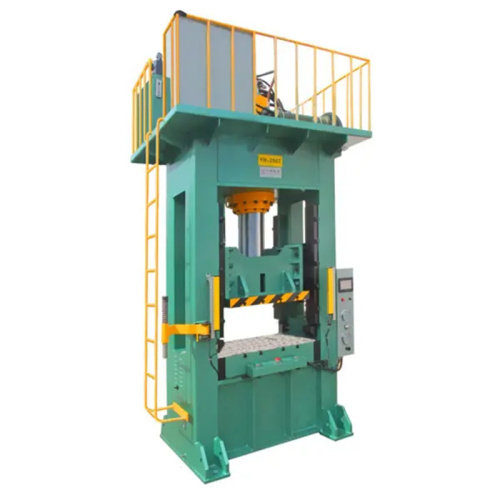
The 40T Hydraulic Press is built for demanding industrial pressing applications, delivering powerful force, dependable operation, and precise control. Its robust construction supports consistent pe
Say goodbye to frustrating jams and experience smoother, more reliable performance with 40T. Designed to help keep operations running efficiently, 40T delivers dependable results when you need them
Email to this supplier

September 22, 2026

September 21, 2026
Contact

Send Inquiry
PRODUCT CATEGORIES
Privacy statement: Your privacy is very important to Us. Our company promises not to disclose your personal information to any external company with out your explicit permission.
Fill in more information so that we can get in touch with you faster
Privacy statement: Your privacy is very important to Us. Our company promises not to disclose your personal information to any external company with out your explicit permission.